Welcome to wziep.com!


Categories
Welcome to wziep.com!


category: Power Meters
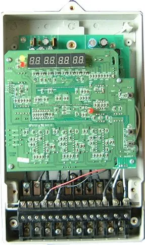
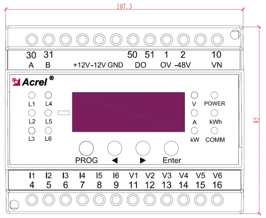
AMC16-DE6 Is an economical and practical multi-channel DC current measuring device. Which collect, monitoring and control the DC current.
Electrical parameter measuring
6 channels voltage, current, active power, active energy.
Switch State
6 channels DI, 1 channel DO
voltage | measuring range | DC35~60V |
overload | instant 2 times/30s | |
current | hall sensor | voltage input: 0-5V |
measuring range | 0-2000A | |
overload | Continue 1.2time, instant 10 times/5s | |
auxiliary power | DC48V±20% | |
accuracy | current voltage | 0.5 |
power, energy | 1.0 | |
consumption | <5VA | |
relay output | 5A 250VAC/5A 30VDC | |
environment | working temperature | -10℃~55℃ |
storage temperature | -20℃~70℃ | |
relative humidity | ≤93% | |
altitude | ≤2500m | |
communication | RS485 | |
parameter checking
Press“←” to inquire as per group
the group is distinguished as per the items
V-voltage, A-current, Kw-active power, Kwh-active energy, switch-“-”open,“r”close
Press“→” to inquire as per phase
L1,L2,L3,L4,L5,L6 represents channel 1-6;
Current, power shows the primary value, energy shows the primary value, and shows the high and low level. When A, Kw, Kwh indicators are all on, means energy is in high level. V, A, Kwh represents energy low level.
i.e. inquires 1 channel energy H1234kWh,L 56.78kWh,this value means 123456.78kWh;
When the energy is larger than 999999.99kwh, it reserve one decimal.
parameter setting
press“PROG”->pass->press“Enter”->insert pass word->IE(primary current/1 channel->6 channel)->addr(address setting)->baud(baud setting)->codE(password setting)->clr.E(Power reset)->zEro(zero calibration)->“PROG”withdraw ->savE(press“Enter”save the setting/press“PROG”cancel the setting)
Press “←/→” to modify the value,“→”to change the menu.
In zEro item, press”←”and Enter can process the zero calibration,select yEs or no.
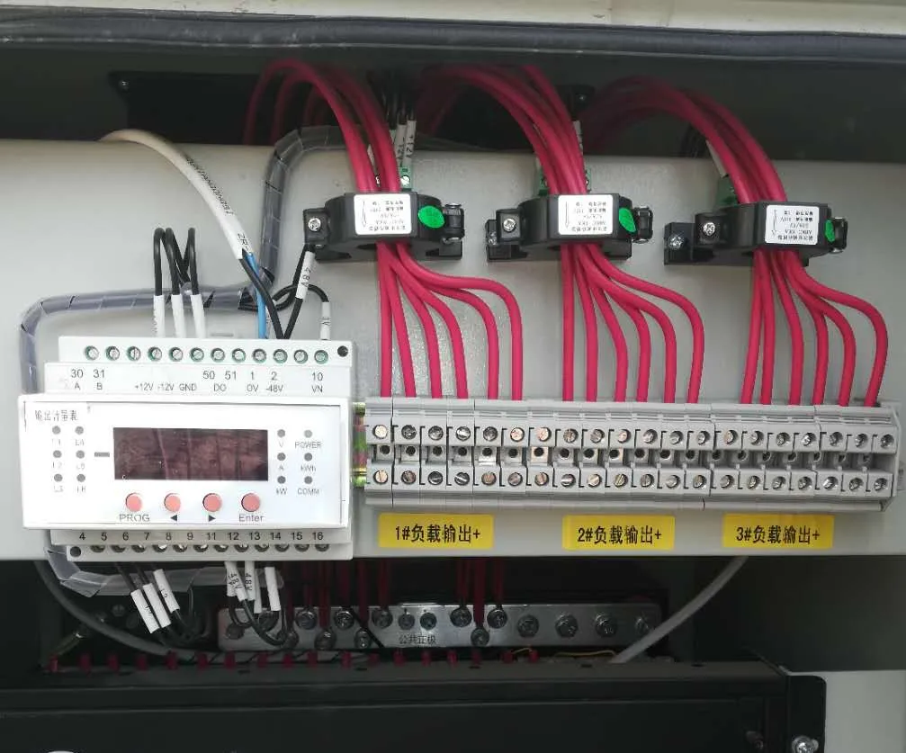
terminals
1,2 | auxiliary power |
4-9 | current 1-6, hall effect sensor signal input |
11-16 | voltage negative |
10 | voltage positive |
30,31 | RS485 |
50,51 | DO output |
+12V | +12V voltage output |
-12V | -12V voltage output |
GND | voltage type hall sensor output negative insert. |
wiring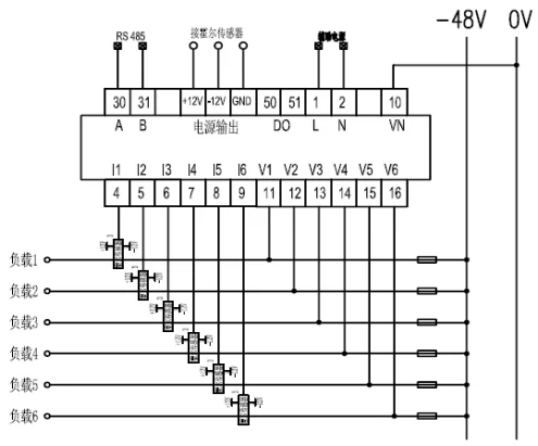 Hall sensor powered by the build-in
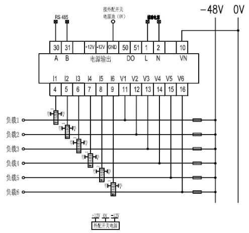
Hall sensor powered by external power
installation
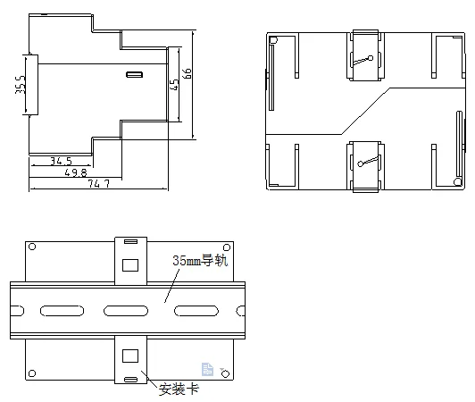
notice
The device should be installed in a dry, clean place away from heat source and strong electromagnetic field
When the hall sensor goes through the heart, pay attention to the current direction, otherwise the measurement will be inaccurate
The current input must use hall sensor, and the current value of each circuit can be set separately
If it is not necessary to detect the switching state, only 1-channel voltage signal can be connected to terminal 10 and 11, that is, the 1-channel voltage
Communication cables shall be shielded twisted pair
Note whether the hall sensor is matched with the required input signal of the device (the hall sensor output is required to be 0-5v).
If the device is used to power multiple hall sensors, the phenomenon of on-load and on-off may occur. At this time, an external power supply should be used to power the hall sensor, and GND terminal on the device should be connected to the external power supply


Analysis of common faults and causes
The measurement of the device is not accurate
Check whether the positive and negative terminals of the voltage are correct
Is the current passing through the hall sensor in the right direction
Check whether the IE setting of the device is consistent with the hall sensor used
Whether the output signal of hall sensor matches the required input signal of the device;
Check whether the output negative pole of the voltage output hall sensor is connected to the device GND
Abnormal communication
Check whether the communication cable is connected normally
Check whether the A and B terminals of communication are staggered
Check whether the device address is set correctly and the communication baud rate is set correctly
Multi - device communication is not normal, first try the single communication, to see if it is normal.
The device does not display properly
Check whether it is caused by the insufficient carrying capacity of the built-in power supply to the hall sensor. Replace the external switching power supply to power hall