Welcome to wziep.com!


Categories
Welcome to wziep.com!


category: Energy Meters
reference price:¥$56.00 - $58.00


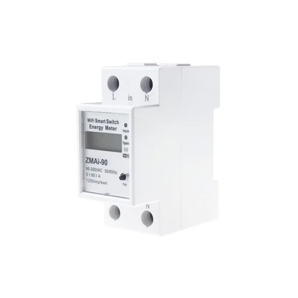
DIN RAIL TYPE THREE PHASE SMART WIFI ENERGY METER
USER’S MANUAL
1. General Description
DTS238-7 WIFI type multi-function smart energy meter is designed to measure three phase four wire AC active energy and variable parameter. The meter have RS485 communication port and WIFI communication, it can use APP for remote reading and control on/off. All of its functions comply with the relative technical requirement for class 1 three phase watt hour meter in IEC62053-21 and its data communication rules obey the requirement of MODBUS-RTU and WIFI 802.11b/g/n.It is a long life meter with the advantage of high stability , high over load capability , low power loss and small volume.
The meter should be installed in suitable environment with ambient temperature range between -25℃~+55℃,the relative humidity less than 75% and temperature limits between and-40℃~+70℃.
The meter is manufactured complying with international standard IEC62052-11 on “Electricity metering equipment (AC) General requirements tests and test conditions” and IEC62053-21 on “Static meters for active energy (classes 1 and 2)”.
2.Specification and Technical Parameters
2.1Specification:
|
Meter type |
DTS238-7 WIFI |
|
Rate frequency |
50 or 60 Hz |
|
Rated current |
1.5(6)A, 5A/CT, 5(60)A ,10(80)A |
|
Rate voltage |
3x120/208V , 3x220/380V , 3x230/400V , 3x240/415V |
|
Normal voltage range |
90%Un~110%Un |
|
Limits voltage range |
70%Un~120%Un |
|
kWh Accuracy |
Class 1 |
|
R.M.S accuracy |
Class 0.5 |
|
Pulse constant |
See meter |
|
RS485 port |
MODBUS-RTU protocol, 1200~9600bps,None parity ,default 9600bps |
|
WIFI |
802.11b/g/n ,only support 2.4GHz network , not support 5GHz network |
2.2 basic parameters:
|
Delayed power on/off time |
60+5s |
|
overvoltage / undervoltage / overload event judgment time |
3s |
|
Overvoltage protection value |
270V+1(default),APP can set value |
|
Overvoltage recovery value |
260V+1(default)= (APP overvoltage value - 10V) |
|
Undervoltage protection value |
170V+1(default),APP can set value |
|
Undervoltage recovery value |
170V+1, (default)= (APP overvoltage value + 10V) |
|
Overload protection value |
65A(default), APP can set value |
|
Delay on/off control |
00:01—24:00 Hour |
Note: when it happens interrupt power-supply , the meter will not cut off , undervoltage event must last 3s , then it will cut off.
2.2 Technical Parameters
2.2.1 Basic tolerance
|
Load Current
|
Power factor (COSφ) |
Basic error (%) |
|
|
Direct connection |
CT connection |
1 |
|
|
0.05Ib≤I<0.1Ib |
0.02Ib≤I<0.05Ib |
1.0 |
±1.5 |
|
0.1Ib≤I≤Imax |
0.05Ib≤I≤Imax |
1.0 |
±1.0 |
|
0.1Ib≤I<0.2Ib |
0.05Ib≤I<0.1Ib |
0.5(L) 0.8(C) |
±1.5 |
|
0.2Ib≤I≤Imax |
0.1Ib≤I≤Imax |
0.5(L) 0.8(C) |
±1.0 |
2.2.2 Self-consumption
Current circuit is less than 1.5VA / each phase
Voltage circuit is less than 2W/8VA each phase
2.2.3 Starting current
Under the rated voltage , rated frequency and COSΦ=1 , the meter shall start and continue to register on application of 0.2% In (if CT is used) or 0.4% Ib .
2.2.4 Anti-creeping
The meter has anti-creeping logical circuit. When 115%Un is connected to the meter and current circuit is cut , the meter shall not create more than one pulse in a stipulated time
2.2.5 Average-life
The meter can be used for at least 10 years in normal operation specified in this manual
2.2.6 LCD: 6+2 (999999.99kWh)
3.Basic Features
4.Working principles
Three phase voltage and current are sampled from respective sampling circuit and transformed into suitable signal, which is carried into integrated circuit , then the meter output pulse signal in positive appropriation to measured power to drive step-motor counter or LCD counter to realize energy measurement. The meter has energy pulse output for testing with pulse width of 80+20ms

5. Structure
The meter consists of meter base , meter cover , terminal base , terminal cover . there are lead seal on meter cover and terminal cover . A special screw is used to fix the terminal cover on which a lead seal can be installed
6. Usage
6.1 schematic diagram


6.1 Connection diagram

Noting: for CT input type connection , the power consumed display in register is not fact power consumed. The fact power= the power display in register of meter X CT rate. For example , the power display in the register is 0.5 kWh and the CT is 800/5A , the fact power consumed=0.5 kWh X 160=80kWh
6.2 Installation

7. Transportation and Storage
8. Warranty period
Within 12 months from the day of selling and provided that users operate correctly according to the requirement of the user’s manual , if the meter doesn’t reach its technical specification. It can be repaired or replaced in free f charge by the manufacturer.
9. Frame format
9.1 Read command(function code 03)
Send frame
|
Meter ID |
Function code |
Register address |
Data number |
Check code (CRC) |
|
1byte |
1byte |
2byte |
2byte |
2byte |
Receive frame
|
Meter ID |
Function code |
Data length n |
Data area |
Check code (CRC) |
|
1byte |
1byte |
1byte |
n byte |
2byte |
10. How to connect wifi for setting up:
1). Please scan the two-bar-codes to download the “WISEN” software
2). Meter input power:
When the meter power on , you can push the setting button last 5s , meter enter into the status of waiting for WIFI distribution network and the WIFI led will flash 1s interval .
its means meter enter into the status of waiting for WIFI distribution network . if WIFI led light on 5s , light off 0.1s ,it means meter connect the WIFI successfully.
3). Add device:
Please check firstly that your telephone have connected the available WIFI network , then click the “add device “ button .now the meter only used under 2.4GHz WIFI network , it can not use under 5GHz WIFI network .
APP Menu instruction
The meter will display online or offline after you add the device successfully .
You can click the device to check the meter detailed information
You will see the active energy data and remote control button and timing setting button in the menu.

Control button : used for control on / off of meter output
Reset button: used for reset the total active energy to zero
Timing button: used for timing control on/off and time delay control on/off
1. time control :you can add the time which is control and which is control off ,if you do not select week , it will save as single time control . if you select the week, it will save as cycle control .
time-delay control : you can set 1minute to 24hour max to time delay control. For example ,you can use delay time control to control off the Battery car charging after 2hours.

the meter do not have time clock internal ,the time control is decide to cloud serve, so make sure the meter connect the available WIFI network.
3.Setting button : for protection value and unit price ,starting active energy value setting.